CAEUp aims at implementing a cloud-based software tool whose core is the comparison of the structural performances between the CAE model relative to the nominal design of a certain product and the digital twin of the real product as built.
The digital twin is updated on HPC cloud infrastructure and the performance prediction recomputed adopting a variation of the CAE model shaped like the actual manufactured part. The process is demonstrated adopting a specific example: the structural assessment of a simplified turbine blade geometry.
The baseline geometry, available as a CAD model, is adopted to define the reference FEA model for the ANSYS® MechanicalTM solver so that key performance indexes can be computed (stress level and stiffness). The actual manufactured shape is surveyed and available as a tesselated surface (the standard STL format is herein adopted). The projection and adaption using mesh morphing allows to morph the baseline FEA model onto the actual manufactured shape; finally the updated FEA model is run again to extract performance indexes and decide whether the component fulfills the design specifications.Robust design concepts
Test case – shape deviation
- The example examines the effects of manufacturing errors on a simplified turbine blade model.
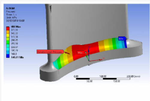
- A scan of the manufactured shape was not available and so a synthetic 3d scanned shape was generated by the application of a variable pressure field on the pressure side fillet and then by updating the shape according to local stress (BGM). A maximum deviation of 0.4 mm was applied.
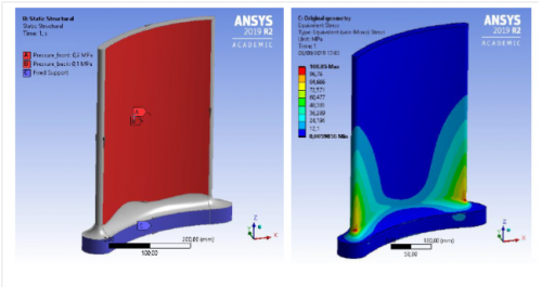
- The shape perturbation was created adopting a fictitious loading condition(root clamped + constant pressure on the airfoil surface)
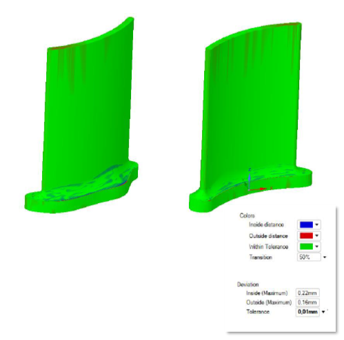
Test case - shape deviation
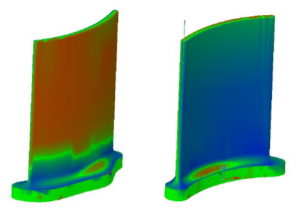
- A colour map is used to show the deviation between the two geometries
- The largest differences are in the fillet area, and the maximum deviation values are 0.38 mm for the inside area and 0.28 mm for the outside area.
Results
- The morphed meshmatches almost perfectly the target model
- The distance of almost all the sample points of the morphed body from the target one is
- less than 0.01mm
- The measured difference between the two geometries is contained within an interval of 0.03mm, that means less than 8% of the manufacturing tolerance.